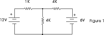
Electrical Tips and TricksSHUNT REGULATORThe lab manuals for many DC circuits courses, including the ones that come with popular text books, have experiments with circuits like the one shown in figure 1.
The problem with them is that sometimes the measured values of voltage and current don't agree with the calculated values. It seems like a mystery: does circuit analysis not always work? Of course it does! The problem is likely to be in the power supply you're using. Circuits like the one in Figure 1 assume that you are using batteries to supply the voltage. An ideal battery will sink current as well as source current. That means that current can flow "backwards" into the battery.
Look at Figure 2 (we are using conventional current here). Using Ohm's Law, we can calculate the current as: E V1 - V2 12 - 6
I = ---- = ---------- = -------- = 6 mA.
R R 1000
But if you are using a typical power supply instead of batteries, you will measure 0 mA. What's more, you will measure 0 Volts across the resistor. What's going on? The answer is that the typical power supply uses a series regulator. A simplified schematic of a series regulator is shown in Figure 3.
If you apply a voltage to the emitter that is greater than what the supply is set to put out, then you reverse bias the transistor. That means that current can flow out the emitter of the transistor, but current can not flow into the emitter. In fact, if too much reverse bias is applied to the transistor it will be damaged. So often a diode is put in series with the output as protection. Is there some way to get a power supply to sink current? Yes there is! You can use a circuit called a shunt regulator.
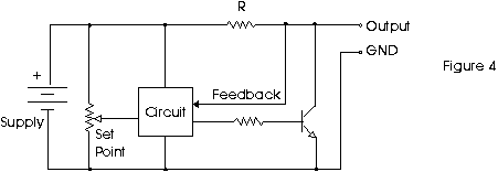
Figure 4 shows a simplified shunt regulator. Note that instead of current going through a transistor to get to the output, the current flows through a resistor to the output. By Ohm's Law, there is going to be a voltage drop across the resistor. The job of the transistor is to conduct just the right amount of current to ground so that the output voltage is at the set value.
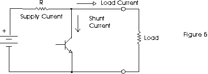
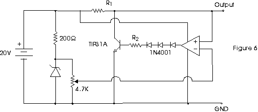
If there is no load on the supply, all the current goes through the transistor. If there is a resistive load, some current goes through the load and the rest goes through the transistor. But here's the important part: if something tries to drive current back into the supply, the transistor will shunt that current to ground as well. Look at Figure 5. Figure 6 shows a practical circuit. The diodes are there because the output of a standard 741 op-amp can not go from "rail-to-rail". So when the 741 output tries to go to zero, it can only go as low as about 2 Volts. That would mean the transistor would always be on, and you wouldn't be able to get maximum output voltage from the regulator. If you use a CMOS op-amp, you won't need the diodes.
You calculate the resistor values as follows: SUPPLY VOLTAGE - MAX OUTPUT VOLTAGE
R1 = --------------------------------------
MAXIMUM OUTPUT CURRENT
2
WATTAGE of R1 = (SUPPLY VOLTAGE) / R1
MAXIMUM SINK CURRENT
BASE CURRENT = --------------------------
MINIMUM BETA of TRANSISTOR
SUPPLY VOLTAGE - DIODE DROP
R2 = -----------------------------
BASE CURRENT
2
WATTAGE of R2 = (MAX CURRENT) x R2
EXAMPLE: 20 V - 10 V 10 V
R1 = -------------- = ----- = 100 Ohms
100 mA 0.1 A
WATTS = (20) x (20) / 100 = 4 W (use a 5 Watt resistor)
200 mA
BASE CURRENT = ------ = 4 mA
50
18 V
R2 = ----- = 4.5 K Ohms (Use 4.7 K Ohms)
4 mA
WATTS = (.004) x (.004) x (4700) = 75 mW (use 1/4 Watt)
You can use a value as low as 1 K for R2 to provide some over-drive capability since a 741 can supply up to 20 mA. If you use a CMOS op-amp, check it's maximum current output. To develop a voltage for the adjustable set-point, we used a 15 V, 1 W zener diode and a 4.7 K trim-pot. To calculate the series resistor for the zener, we just used:
      VOLTAGE DROP     (20  - 15) V
R  =  ------------  =  -------------  =  250 Ohms.  We used 200 Ohms.
     ZENER CURRENT        20 mA


WATTS = (5V) x (5V) / 200 = 125 mW (Use 1/4 Watt)
|


